|
HULL
ASSEMBLY - Hull Openings
|
|
1.
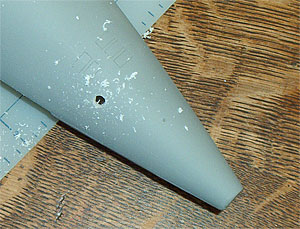
With the stern piece completely cured, it is now time
to open the many holes necessary to correctly model
a Permit class SSN. Using the supplied plans
as a reference, locate the dimple in the hull where
the mushroom anchor is mounted just forward of the lower
rudder. Using an electric drill and a 7/32 bit,
drill out the dimple to receive the cast resin mushroom
anchor. Use a round file to widen the hole to fit if
necessary.
NOTE:
Following the curing of the stern pieces, the Permit
hull depicted was painted with primer. This allowed
the scribed hull opening lines to be more clearly seen
during the drilling process. However, it is not required
that you prime your hull at this time. Details on how
to prime and paint your model will be outlined in section
9 "Detail & Paint".
|
|
|
2.
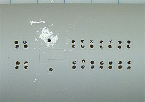
Switch to a 1/8 bit and drill one or two holes
in each Main Ballast Tank flood hole. The MBT floods
are rectangular in shape and there are 5 grouped
just forward of the anchor. These holes will allow
the use of a Dremel grinding bit to further clean out
the opening.
TIP:
Take the time to mark each flood to be opened with a
pencil or marker prior to drilling to prevent mistakes.
|
 |
3.
Moving forward, locate the next set of floods amidships
and drill similar holes in them as well. There are 20
MBT floods in this section.
NOTE:
Do not drill in the T-shaped area scribed in between
the flood groups. This is the cover for the Secondary
Propulsion Motor (SPM) and should be left intact.
|
|
|
4.
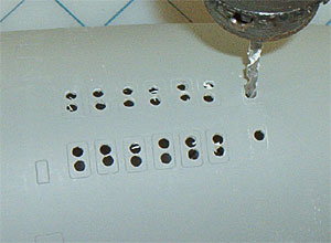
Locate the forward group of floods near the sonar
dome demarcation line. There are 14 scribed rectangles.
Drill pilot holes in each of the floods. |
 |
5.
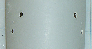
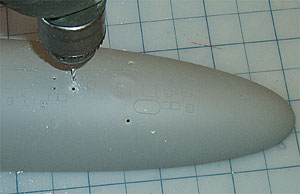
With the floods completed, switch to a 7/32 bit
and drill pilot holes in the two Main Sea Water openings
on either side of the hull. The lower hull opening pilot
holes are now complete. |
 |
6.
On the upper hull you will notice dimples representing
the Main Ballast Tank vent openings. A set of stainless
steel photo-etched parts will accurately depict
the MBT vents and will be installed in a later section.
However, holes must be drilled in the hull to allow
trapped air to escape through each vent during r/c
operations. Using a 3/32 bit, drill a single
hole in the center of each of the 6 MBT vent
dimples in the forward section.
|
 |
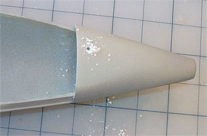
7.
Moving amidships, drill holes in each of these 6
MBT vent dimples. |
 |
8.
Finally, locate and drill the single MBT vent
in the upper stern section of the lower hull. It is
located slightly forward and to starboard of the upper
rudder.
Don't
be alarmed. Though your model may look more like Swiss
cheese than a submarine at this point, it will soon
take on a scale appearance with our next step...
|
| |
Next
|
|
|
Hull
Opening Glossary
Main
Ballast Tank (MBT) vent: Round, stainless steel
vent valve in the top of main ballast tanks that open
to allow air to escape for diving and close to trap
air for surfacing.
Main
Ballast Tank flood/drain: Rectangular opening in
the bottom of main ballast tanks that allow the free
flow of water into, and out of, the tank during diving
and surfacing.
| |