|
SAIL
- Assembly & Mounting
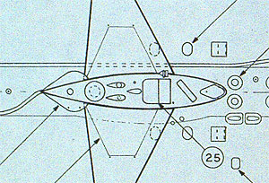 |
1.
For
radio controlled operations, it is necessary to open up
a hole in the top of the sail to allow trapped air to
escape during diving. Study the plans, then choose an
area to open such as a mast or the bridge clamshells.
For this project, the VLF loop antenna opening was selected. |
|
|
2. Using a very small grinding bit, grind out
the VLF loop opening with the Dremel.
NOTE:
periscope and mast assembly/ installation will be outlined
in section 9.
|
|
|
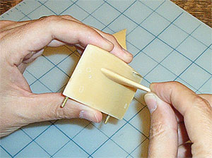
3.
Using round and half-round needle files, file out the
VLF opening to the scribed lines.
|
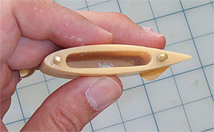 |
4.
Here you can see the opening through the sail top. It
is important that the hole accesses the interior void
of the sail otherwise air will remain trapped inside.
By working files at an angle, the interior side of the
hole can be beveled wider.
With
the VLF opening complete, we can turn our attention
to the sail planes (read side bar "Sail Plane Detour?"
before beginning step 5).
|
|
|
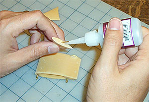
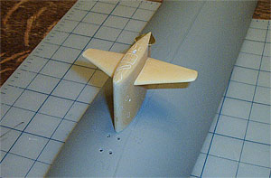
5.
Locate the planes and test fit them in the pre-drilled
mounting holes. They should fit snugly against the sail
and protrude from either side of the sail at a 90°
angle. Both port and starboard planes should be aligned
with one another through the sail. Slight filing of
the mounting holes can correct any variations in alignment.
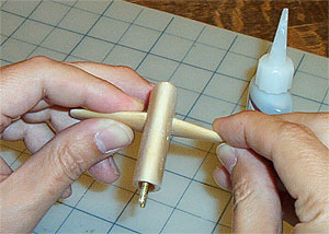
Apply
cyanoacrylate to a plane with the supplied connecting
rod inserted. Apply glue only to the surface which will
rest against the sail side.
|
 |
6.
Slide the connecting rod into the pre-drilled hole and
glue the plane to the sail. Slip the other plane on the
opposite side in order to check the alignment of the two
planes as the one dries. |
 |
7.
Apply glue to the opposite plane and slide it onto the
connecting rod and against the sail. Hold it in place
until the CA dries, then set it aside. |
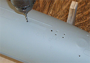 |
8.
Moving to the upper hull, locate the two sail mounting
bolt dimples in the upper hull. They are at the forward
and after end of the scribed sail outline in the hull.
Use a 7/64 bit and drill out the mounting hole
hull dimples. |
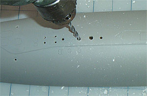 |
9.
Switch to a 3/16 bit and drill two drain
holes on center between the mounting holes. Be sure to
keep the holes within the scribed outline of the sail.
The holes will allow air to escape more quickly from the
lower hull during dives and will quickly drain the sail
during surfacing. NOTE: there is no scribing or dimples
to indicate placement of the holes. Just select a spot
within the sail outline on the centerline of the boat. |
 |
10.
Slip the mounting bolts of the assembled sail into the
holes in the upper hull. DO NOT apply glue to
the sail or upper hull. Install the nuts on the mounting
bolts and tighten until snug. Be careful not to over
tighten. NOTE: using the mounting bolts without applying
glue enables the sail to be removed for transportation
and greatly reduces the risk of accidental damage during
trips to the pond. |
 |
11.
Turn the upper hull over. The sail should be firmly
mounted and rising vertically from the hull. If the
sail leans to port or starboard, unfasten it and gently
sand the underside of the sail to remove the high spot
and bring it into proper alignment. As always, be careful
not to remove too much material at one time.
Your
boat is beginning to look rather smart. It is now time
to work on the essential hull appendages used in radio
controlled operations. First, the rudders...
|
| |
Rudders
|
|
|
Permit
Sails
During
the design stage, it was proposed to completely remove
the sail on the Permit class boats to reduce
underwater drag. However, the impracticality of having
to tow the submarine out to sea at the beginning of
each patrol due to the near zero freeboard quickly negated
the proposal. Instead, the sail was designed with a
minimum height. The sail planes were mounted as high
as possible in an attempt to increase depth control
close to the surface. The final design was so narrow,
one could almost reach through the sail via the maintenance
access plates.
|
|
Sail
Plane Detour?
Because
of their small size in 1/96 scale, the kit's sail planes
afford minimal control influence during r/c operations.
Thus ThorDesign recommends mounting them in a fixed
position. However, if active sail planes are desired,
skip steps 5 - 7 and use the plane connecting rod as
your control shaft. By mounting a bellcrank on the shaft
and running the linkage through the sail and into the
hull, you can effectively animate them.
|
|