|
DRIVE
TRAIN - WTC Saddle Installation
 |
1.
First, the location of the WTC and its mounting saddles
must be established. Locate the WTC as far forward in
the hull as possible without hitting the indexing lip.
The saddles should be spaced far enough apart to evenly
support the WTC. Take care that the saddles do not interfere
with the flood/drain holes in the lower hull or the ballast
tank flood/drain holes in the WTC. Once the proper saddle
locations are determined, mark the edge of the indexing
lip on the lower hull. |
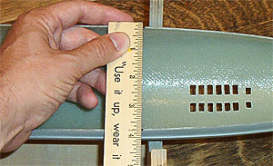 |
2. Measure the maximum lower hull inner width at
the marks. Divide the hull width by two. The sum is the
template radius. |
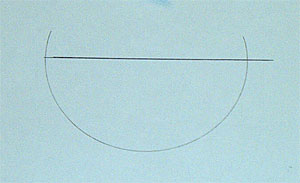 |
3.
On a piece of card stock, draw a straight line. This will
represent the horizontal centerline of the the hull cross
section. Set a drafting compass to the template radius
and draw a template for the hull cross section using the
horizontal centerline. Cut the template out. |
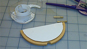 |
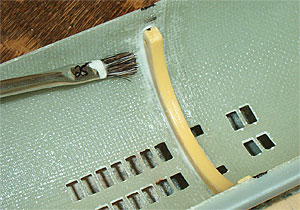
4. Remove the brass rods from a WTC saddle (pliers
and a gentle twist should do it). Tape the template
to the saddle. |
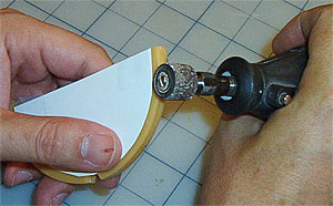 |
5.
Using a Dremel with a sanding drum, trim the exterior
of the saddle to the shape of the template. Work carefully,
removing just enough to meet the template. Repeat steps
4 - 5 for the second saddle. NOTE: a hobby sized belt
sander makes short work of this process. |
 |
6.
Test fit the saddles in the hull. Sand and file
down the high spots until you achieve a good, close
fit. Make sure the saddles just meet the hull and are
not wedged in.
NOTE:
A fit that is too snug can cause the hull to distort
slightly, interfering with the mating of the upper hull
over the indexing lip. Double check the fit of the upper
and lower hull with the saddles in place before proceeding.
|
 |
7.
To ensure the proper operation of the automatic pitch
controller in your WTC (ThorDesign recommends the PC-2
Intelligent Pitch Control), the cylinder
must be properly oriented in the hull with a zero bubble.
Begin by using a vial level to make sure your Permit
hull is perfectly level on its stand.
|
 |
8.
Place the saddles in the hull and lay your WTC in
the saddles. Check the WTC's attitude with the vial
level. It should be perfectly level, along the hull's
longitudinal axis. If it is out of level, carefully
sand down the outside of the high saddle until
the WTC is level.
|
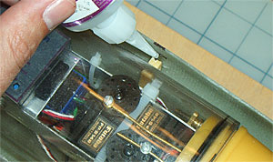 |
9.
Sand the hull interior and saddles to rough up the
surface where they will be joined. Place the saddles in
the hull and install the WTC. Check the WTC's attitude
with the level. If it is at zero bubble, apply a drop
of CA between the top of each saddle and the hull. Capillary
action will draw the CA into the space and tack the saddles
in place. |
 |
10.
Remove the WTC. Brush a batch of 50/50 epoxy & micro-balloons
into the seams between the saddles and the hull. Build
a fillet around the base of each saddle with the epoxy.
Set the hull aside and allow the epoxy to cure completely. |
| |
Next |
|
|
Note
from Matt:
Beginning in June, 2003, all Permit kits will
contain upgraded WTC saddles. These parts will already
be sized to fit the Permit hull diameter, thus
eliminating the need for steps 2 - 5 as depicted on
this page.
In
addition, all kits will come with a UC-2 universal coupling
which consists of two brass universal couplers and a
dog bone connector. |
|
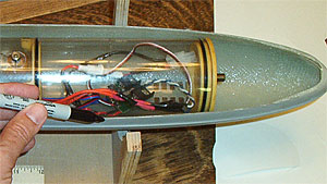
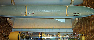
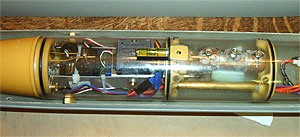
A
Word About WTC's
To
equip your Permit for R/C operations, you will
have to either build or purchase a watertight cylinder
(WTC). These units house all the necessary electronics
and gear while keeping the water out. Given the Permit's
dimensions in 1/96 scale, a 3" diameter cylinder
is the best size to use. Currently, ThorDesign is nearing
completion on a WTC for all our kits. However, in these
instructions a WTC-3 from D&E Miniatures is depicted.
|
|
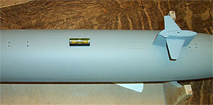
Watch Your Attitude
Be sure to check the attitude of the WTC's drive shaft.
It should rest level at the hull's horizontal center
line and be centered on the hull's longitudinal axis.
One should be able to draw a straight, imaginary line
down the center of the hull, from the drive shaft to
the center of the stern where the prop shaft will exit.
Making this alignment true minimizes drive train vibration
during operations. |
|