1.
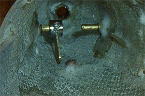
To avoid the propeller shaft, the stern plane linkage
will use split control collars and linked control rods.
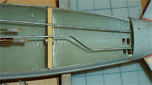
Insert the control collars onto the stern plane control
shafts and tighten the set screws. Check the control
horns for movement. If they bind against the hull, remove
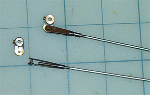
them and trim the control horn to ensure proper clearance.
2.
Remove the stern plane control collars. Drill a
1/16" hole in the center of each control horn as
shown. Insert a clevis in the hole in each control horn.
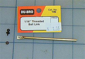
Thread a length of rod into the clevis. NOTE: Most hobby
stores sell prefabbed Du-Bro rod & clevis sets.
However, they can be purchased separately and assembled.
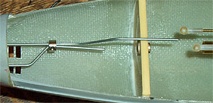
3.
Reinstall the control collars. Work the control rods to
make sure the stern planes do not bind. Bend the port
control rod forward of the wheel collar up at approximately
45°. With the lower part of the control rods parallel
to the boats longitudinal axis, bend the port rod back
down until it is parallel with the WTC control rod. Mark
the port stern plane rod 2" from the WTC control
rods. Cut the port rod at the mark.
4.
To join the control rods, bend the starboard rod with
pliers 45° so that it crosses the port rod. Bend the
starboard rod back parallel to the port rod where they
cross. Mark off 1/2" of overlap on the starboard
rod. Cut the starboard rod at the mark. Slip the supplied
wheel collar onto the two control rods. Center the stern
planes and tighten the collar. Manipulate the stern planes
via the control rods. They should operate in tandem without
binding. Adjust the rods in the wheel collar as necessary
until the stern planes operate correctly, then tighten
the set screw.
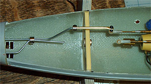
5.
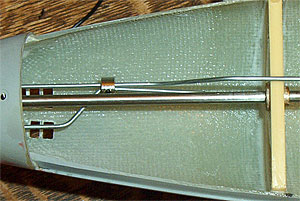
NOTE: The combined control rods should come together
below the prop shaft. The port rod is bent so that it
will rise and meet the WTC control rod. At no time should
the contact the shaft.
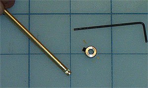
6.
Cut a 3" length of brass tube. Flatten 1/4"
of one end of the tube with a hammer. Drill a 1/16"
hole in the flattened area and insert a ball link.
7.
Drill a 3/32" hole in the top of the tube at the
open end as shown. Place a wheel collar over the open
end of the tube and tighten the set screw until it enters
the hole.
8.
Slide the brass tube onto the port stern plane control
rod. Snap the ball connector into the plastic quick
connect threaded onto the WTC control rod. Center the
stern planes and tighten the wheel collar until it secures
the stern plane control rod to the brass control tube.
Power up your radio and WTC and check stern plane operation.
They should respond in tandem without binding.
With
the boat assembled, WTC installed and linkages in place,
it is time to get wet...