 |
1.
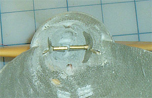
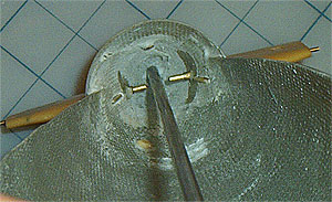
Prior to installing the stern planes and appendages,
care must be taken to ensure proper clearance of the propeller
shaft between the stern plane control shafts. Here one
can see that the control shafts are almost touching. This
would prevent passage of the prop shaft down the center
of the boat. Thus, the control shafts must be shortened. |
 |
2.
Working with one stern plane set at a time, mount a
control collar on the fully inserted control shaft.
Leave about 1/32 between the collar and the installed
bearing. With a sharpie, mark the exposed end of the
control shaft.
NOTE:
If necessary, file down the control arm on the collar
for proper hull clearance.
|
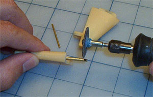 |
3.
Using a Dremel and cutoff wheel, remove the excess control
shaft at the sharpie mark. File the new control shaft
ends smooth. |
 |
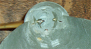
4.
With the shortened control shafts installed, insert
the propeller shaft to test fit. Plenty of clearance is
available now. It is time to permanently install the stern
planes and affix the appendages to the hull. |
 |
5.
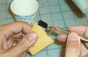
Mix a 50/50 batch of epoxy and micro-balloons. Apply
the epoxy with a brush to the appendage mounting tab.
WARNING:
Do not allow epoxy to encounter the stern plane
or control shaft, only the hull end of the appendage
and the mounting tab.
|
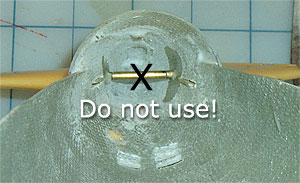 |
6.
Insert the stern plane control shaft into the bearing
and slide the mounting tab into the hull. Do the same
for the opposite side.
IMPORTANT:
Do not use the brass control shaft connecting
tube used during bearing installation. Once the appendages
are cured, the tube cannot be removed and will prevent
installation of the propeller shaft and stern plane
control collars.
|
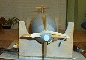 |
7.
Secure the stern plane appendages in their proper
location with masking tape. Double check for proper alignment.
Set aside and allow to cure overnight. |
 |
8.
With the control surfaces installed, the
next section will provide a scale metal propeller and
mounting saddles for a water tight cylinder (WTC) to
enable your boat to get underway...
|
| |
Drive
Train/WTC
|