|
STERN
PLANES - Bearing Fabrication and Alignment
|
|
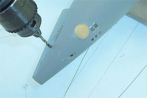
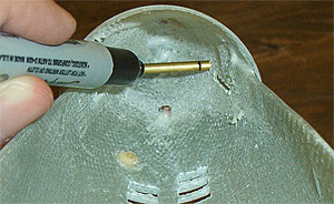
1.
Using the existing control shaft holes as pilots, drill
out the mounting holes for the stern plane bearings
with a 3/32" bit.
|
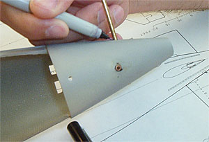 |
2.
Insert a length of 1/8" o.d. (3/32"
i.d.) brass tubing into the starboard stern plane bearing
hole. Extend the end of the tubing through the port
stern plane bearing hole until it is flush with the
exterior of the hull. Then mark the tubing with a sharpie
at the starboard stern plane hole so the mark is flush
with the exterior of the hull.
|
|
|
3.
Cut the tubing on the sharpie mark and de-burr the
freshly cut end with a round needle file. The control
shaft of the stern planes should slip into each end
of the tube and rotate without binding. |
 |
4.
Slip the tube back into the holes in the hull. Make marks
on the tube with a sharpie approximately 1/8 inch
from the hull on both ends. |
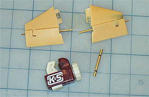 |
5.
Cut the tube on each mark. The two small pieces will
be used as the port and starboard stern plane bearings.
Do not discard the center section of the tube.
It will be used in the gluing process. De-burr all three
pieces of tubing to ensure that the control shafts do
not bind. |
 |
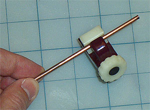
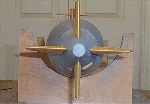
6.
Place the port stern plane assembly in the hull with
the bearing on the control shaft. Slip the longer, middle
tubing piece over the shaft. With the bearing on the
control shaft, insert the starboard stern plane assembly
into the hull and the middle connecting tubing.
NOTE:
The
middle brass tubing piece, though it won't be used in
the final operational rudder setup, serves to keep the
bearings properly located in the hull holes for gluing
and keeps the control shafts properly aligned.
|
 |
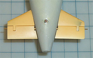
7.
Recheck the stern plane alignment at this time.
When viewed from astern, the trailing edges should form
a horizontal line through the center of the hull. If
any correction needs to be made, use a round needle
file on the hull holes. REMEMBER: a little filing goes
a long way on the alignment of these holes. Work carefully.
Once
everything checks out, it is time to glue the bearings
in place...
|
| |
Next
|
|
|
Glossary
Stern
Plane: Moveable horizontal control surface.
Appendage:
Fixed, triangular vane on which the stern plane is mounted.
Control
Shaft: Brass shaft molded into the stern plane on
which the control linkage is mounted.
Mounting
Tab: Flat,
carbon reinforced extension in the stern plane appendage
which is inserted into a slot cut in the hull. Provides
mounting support for the appendage.
|
|